

Subsea pumping stations are one of the most equitable solutions for increasing oil recovery from subsea wells in operation today.
The seabed pumps improve production by reducing backpressure on the reservoirs which results in increased product flow rates and increased recoverable reserves.
The subsea pumps are also be used to inject water into the less efficient reservoirs to increase pressure, recovery and production rates.
Benefit of subsea pumps
- Increase production
- Increases recovery and increases extends the working like of the field
- Allows production from otherwise reservoirs of low reserves
- Reduces operating cost significantly
- Increases flow assurance performance
- Provides safer and quicker start-up of low energy wells
However, the subsea environment for all equipment, including electrical equipment, is extremely challenging. An integral part of subsea pumps are the variable frequency drives (VFDs) which provide the pumps with essential variable speed capability.
VFDs are absolutely fundamental to the success of subsea pumping station and arguably to the oil industry itself. However, the VFDs and associated transformers can be very large and heavy, especially if multi-pulse designs (to reduce harmonic distortion on the platform) are utilised.
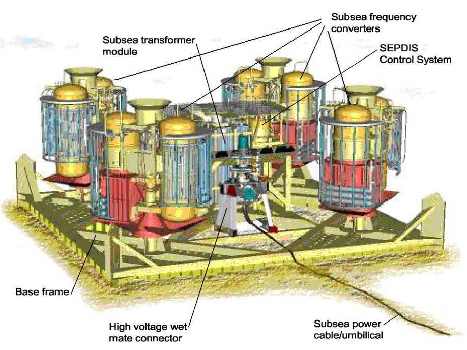
The illustration below provides an artist’s impression of a small subsea pumping station complete with transformers and VFDs.

Subsea multi-phase pump stations comprise a number of discrete pumps, each often complete with its own transformer and VFD (i.e. shown as frequency converters above). As the oilfields increase in size, the power requirements will be considerable. The schematic below shows a subsea pumping field utilizing conventional VFDs.
")
As can be seen above, the overall system comprises of a 13.8kV AC supply ‘topside’ (i.e. on the platform) and subsea transmission line, which is then fed via subsea transformer and circuit breakers to the four subsea pump modules, three of which contains four (4) 1200kW/1600HP VFDs, each with a dedicated 12 pulse phase shift transformer (i.e. harmonic mitigation). The fourth subsea module has three (3) transformer/VFD sets.
The total number of transformers is twenty-one (21); fifteen phase shift types for the VFDs. Each would be in the order of 1400-1500kVA. In addition, there are four transformers, one for each subsea pumping module (around 5-6MVA each). The transformers at each end of the transmission line would be in the order of 20MVA.
Even though each subsea VFD has a 12-phase configuration, the harmonic voltage distortion (THDu) topside would likely be significant and would exceed any marine and offshore harmonic recommendations. Therefore, harmonic mitigation would also be required on the platform. In addition, as the transmission line utilized AC voltage, the maximum distance to the pump field from the platform or shore is limited due to the cable capacitance.
Using the original schematic for the conventional VFD approach, an alternative design concept has been suggested below utilising a Resonant Link DC power system.

The above depicts the same subsea system regards the number of pump modules and pumps but based on a Resonant Link MVDC transmission and common DC bus system via AC-DC active transformers. Note that the common DC bus system depicted above was to match (as far as possible) the original design of the conventional system. However, a DC ring main would be more suitable in type of application; the main advantage being security of supply since the DC power is provided from two sides.
The supply voltage proposed from topside (i.e. the platform or shore) to subsea via the 20kVDC Resonant Link 13.8kVAC/20kVDC active transformer. The DC voltage selected is usually determined by the available DC cable availability and cable cost optimization. This optimization has to take into consideration the power requirement and cable length.
The transmission system shown is designed for that cable operating voltage of 20kVDC. 50kVDC may be a better choice, depending on a number of factors. The use of DC permits power to be transmitted far longer distances from the platform or form the shore than possible with AC transmission systems. Once subsea, the DC voltage is ‘transformed’ to a regulated 6kVDC, this being the required DC bus voltage for the VFD IBGT inverters which controls each subsea pump.
Each Resonant Link AC-DC active transformer has an inbuilt high frequency transformer and input and output overcurrent and short circuit protection. The space requirements and weight for a subsea pumping system based on Resonant Link technology is a fraction of that required for the conventional system.
Topside, the <2% THDi virtually eliminates the total harmonic voltage distortion due directly to the subsea pumping station. The active transformers also regulate the output DC voltage and maintains input displacement power factor at unity or as desired. Both AC line and DC short circuit protection is provided within the active transformers. No additional protection is required. Resonant Link semiconductor switches can, due to the soft switching strategy, interrupt AC or DC current safely and faster than any circuit-breakers. For reliability, the active transformers are multi-module with built-in redundancy and have automatic hot-swapping capability in event of a failure.
Overall, the reduction in both first cost and life cycle cost of a subsea pump systems would be very significant indeed with the adoption of a Resonant Link DC power system.
Note: Resonant Link can also be utilised for standard medium to high powered (<50MW) HVDC transmission systems, either from topside to subsea, platform to platform or from shore to platform.
