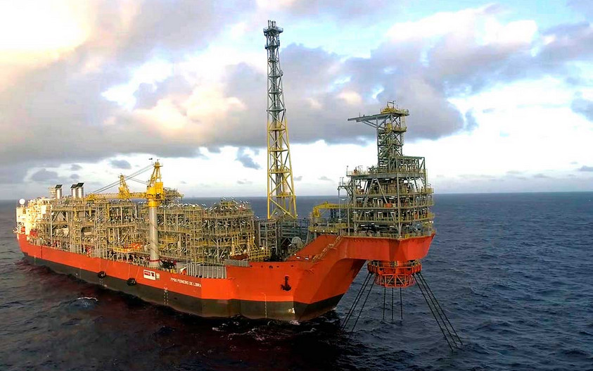
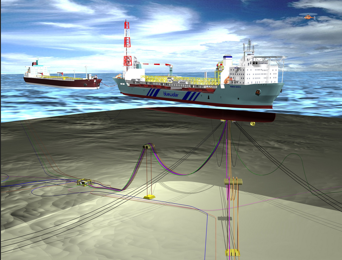
FPSO (floating, production, storage and offloading) vessels today are the primary means of treating, storing and transferring (i.e. to shuttle tankers) product in the majority of offshore oil and gas producing regions around the world.
An FPSO vessel (see below) is a floating production system that receives fluids including crude oil and water from subsea reservoirs.
Most FPSOs are ship-shaped, often rebuild from older tankers and are ‘anchored’ (moored) by a ‘turret; (i.e. a ‘turret mooring system’ is defined as a mooring system where lines are connected to the turret which via bearings allows the vessel to rotate around the anchor legs).

Many FPSOs have also electrically drive thrusters, usually via AC VFDs or controllable pitch propellers on older vessels, to maintain station. The type of turret used is determined by the environment of the FPSO. In calmer waters, spread mooring is often sufficient. In environments where cyclones or hurricanes occur, dis-connectable mooring systems are used so that the vessel can be taken out of the storm’s way and replaced when the storm has passed.
In recent years there has been a growing trend towards FPSOs in ultra-deep water (i.e. >2000 metres/6500 feet) worldwide, including Brazil, West Africa, North Sea and the Gulf of Mexico. At these depths the more attractive and cost-efficient solution of is that ‘dynamic positioning’ where essentially the FPSO ‘hovers’ by mean of variable speed thrusters and GPS control technology.

Typical dynamically positioned FPSOs can have up to 6 off 3-6MW thrusters, usually controlled by AC VFDs. Irrespective of whether the FPSO is turret-moored, assisted dynamically-positioned turret moored or fully dynamically positioned, the FPSO also requires significant power to operated pumps, fans, compressors and other applications, a significant number of these is via AC VFDs.
From around 2008 FPSOs can have an installed base of VFDs in excess of 100MW, with single application VFDs to 36MW. This installed capacity of VFDs often pose considerable challenges to the vessel’s power system from the space, harmonic voltage distortion and EMC perspectives.
A common solution for higher power (i.e. 700kW-2000kW) VFDs in the oil industry is to use 18, 24 or 36 pulse VFDs which require appropriate phase shift transformers. In addition, these VFDs require required multiple input rectifiers. In these VFDs the phase shift transformers in large and very heavy, especially so in the case of the 36 pulse VFD.
A leading ESP (electrical submersible pump) manufacturer provides 36 pulse MV VFDs (3.3-6.6kV) up to 1500kW for FPSOs. The physical size of a 1500kW version is 2718 H x 5639 W x 1828 D (mm); nett weight 11,200kg.
The sheer space requirement (28 cu.m.) for each of these VFDs often determines the number of ESPs which can be installed onboard and thus limiting the production and subsequent profitability. In comparison, a Resonant Link VFD at 4.16kV, 60Hz and 1500kW would require less than 5 cu.m. of space.
FPSOs are also ideal candidates for Resonant Link DC common bus or ring mains which provide DC voltage to the VFD IGBT inverters (output stages). One significant benefit of a Resonant Link DC power system is the tremendous reduction in the total VFD footprint on FPSOs, production platforms and other installations, since the very large phase shift transformers are not required.
For example, the 1500kW, 36 pulse ESP VFD mentioned above each requires is 28 cu.m. On the basis there are ten (10) such ESP VFDs installed on board the FPSO, the total space required is around 280 cu.m. The 1500kW PWM IGBT inverter (module only) is estimated at around 4.2cu.m. Ten (10) such PWM IGBT inverter modules would require a total of 42 cu.m. of space.
10 off 1500kW IGBT VFD modules would require a Resonant Link AC-DC active transformer of around 16MVA with a space requirement of around 5-6 cu.m. depending on the voltage. Total cu.m. for Resonant Link DC power system for 10 off 1500kW ESP VFD system would be around 50 cu.m (including the 10 off IGBT VFD modules), some 17% of the volume required the 36 pulse, 1500kW, 36 pulse VFDs.
It should be obvious that more ESPs could be installed (given sufficient generator power available) to increase production by installing a Resonant Link DC power system to drive the ESP VFD (and medium to large VFDs onboard).
Resonant Link VFDs and DC systems have virtually harmonic-less (THDi <2%. This applies to VFD output also). On VFDs the dv/dt (rate of rise of voltage) is <20V/μs, a 1000th of that of PWM VFDs. The often troublesome common mode voltage experienced with PWM VFDs does not exist.

